Deleted
Deleted Member
Posts: 0
|
Post by Deleted on Oct 10, 2014 8:55:24 GMT -5
Admin Editors note: the info below also applies to the Terrova - freshwater version of the Riptide. Though if you have a Terrova with the built-in sonar then you may already be grounded...So I chose to ground the TM motor on my Riptide internally rather than externally. Luckily for me, there were no instructions to confuse me. Although, I did have a few conversations with people who like to over complicate things because they are geniuses.  The bottom line is that you will have to do some thinking on your feet. The steps are: - Take apart bottom unit by removing the wing nut for the prop and the two long bolts. This will allow you to remove the nose cone and will expose the motor shaft. You can now pull the motor out from the nose cone side. See pics. You will have to use some force.
- Take apart control head and fish something down the shaft. I used weed eater line. Then follow this with the wire you are going to attach.
- Attach the wire to one of the hex nuts that holds down the brush plate on the side opposite of the nose cone.
- Use your brain to figure out the best method for putting things back together properly. This took some thinking and a few mistakes before getting it. My best advice is to just think for yourself and have confidence that you can figure it out.
PICTURES: After removing the prop:  The section with skeg that comes apart. This is where you attach the ground wire.  Inside view after motor is removed. Note, those things are rather powerful magnets, so you have to pull rather hard. 
|
|
Deleted
Deleted Member
Posts: 0
|
Post by Deleted on Oct 10, 2014 9:00:50 GMT -5
Rather than attach the ground wire to some ground in the control head, I decided to run my wire to the base of the unit. This eliminated the need for cutting very small control wires and having to solder. I also decided to put a fuse on the ground wire just in case it touches something bad. Motor  Fused wire in control head  View of wire going into base. Rather than splice anything I just simply ran this wire to the plug and clamped her down.  If anyone needs further clarification, please feel free to ask. I have no clue if this has provided me any value. However, I do know that I did it right because I if I touch my meter lead to the wing nut metal and to my ground battery for my TM, I get continuity! I will need to get on the water to see if this has removed the interference that really wasn't interfering with anything. Cheers, Yam |
|
|
|
Post by mwardncsu on Oct 10, 2014 9:49:26 GMT -5
Was good collaborating on the tear-down & options... With the iPilot I think running the ground wire down to the base is definitely the way to go - no reasonable options for grounding in the head unit like with the CoPilot / Autopilot units. And this is really not all that hard.... However - on the topic of over complicating things - leave the shaft-seals alone unless there are obvious signs of failure - when 1st dissembling the lower unit I thought they would pop out to gain some access to disassemble and I possibly damaged the outer seal may or may not have but wanted to put new ones in just to be certain they were OK. I had new seals as they came with a kit for new o-rings (which I did use) - but I'll be damned if I can't get the seals out to replace - talked with MinnKota as well as another shop this AM and both told me the way I was trying was right - may have to break out the heat-gun - or more likely take it to the shop and let them replace....  But my grounding wire looks nice as does my new xducer running down the shaft......  The other up-side is if needed I could field-strip a trolling motor and likely get things back up and running (assuming its not a stuck shaft seal  ). If you don't take stuff apart, then how are you every going to learn how things work..... its been a character flaw since my early childhood days  |
|
Brian
New Member
Posts: 611
|
Post by Brian on Oct 10, 2014 9:54:12 GMT -5
Did you run the ducer wire inside the shaft or did you dremel out the exterior groove like yam?
|
|
Deleted
Deleted Member
Posts: 0
|
Post by Deleted on Oct 10, 2014 10:10:46 GMT -5
Did you run the ducer wire inside the shaft or did you dremel out the exterior groove like yam? You can't run the ducer wire up the shaft unless you drill a hole. DING! Given that I was able to seal my boat after drilling 1/2 inch holes in the boat for my exterior lights, I am guessing I can seal a hole in the motor casing. Dammmit Brian! I'm not doing this! MY external thing work great. And yes, MWard "routed" (which took 10 times longer) his shaft! |
|
|
|
Post by mwardncsu on Oct 10, 2014 10:23:06 GMT -5
Grounding wire was done the same as Yam - connected to a mounting screw that holds the motor brush assembly to the housing with the skeg and then routed the wire up the inside of the shaft and into the head. From there routed the wire out the bottom of the head through one of the existing drain holes - close to the cable that connects the head to the base. Ran the wire down the middle of this coiled cable and zip tied along the power cable and connected to the ground terminal in the trolling motor plug.
Don't forget to also connect your TM battery ground to whatever battery you use to power your fish finder (recommended to use a 2a or so fuse on this link).
|
|
|
|
Post by mwardncsu on Oct 10, 2014 10:50:22 GMT -5
Sorry Brian - I misread. I ran the xducer wire external. Not sure if you could get the connector through the shaft even if you first remove the power wires. And like you say you'd have to drill a big hole in the motor housing - and there is not a lot of room to turn a bulk wire up and up te shaft to be out of the way of the shaft/coils. But yes - I setup a jig and broke out the router.  . Though a high-speed steel "dome" bit does not cut as easily as just using a Dremel with the drum sandpaper bit - go figure.....  . I came back with the Dremel to clean up the grove and get is a consistent dept so it won't "stick" when sliding the motor up / down. 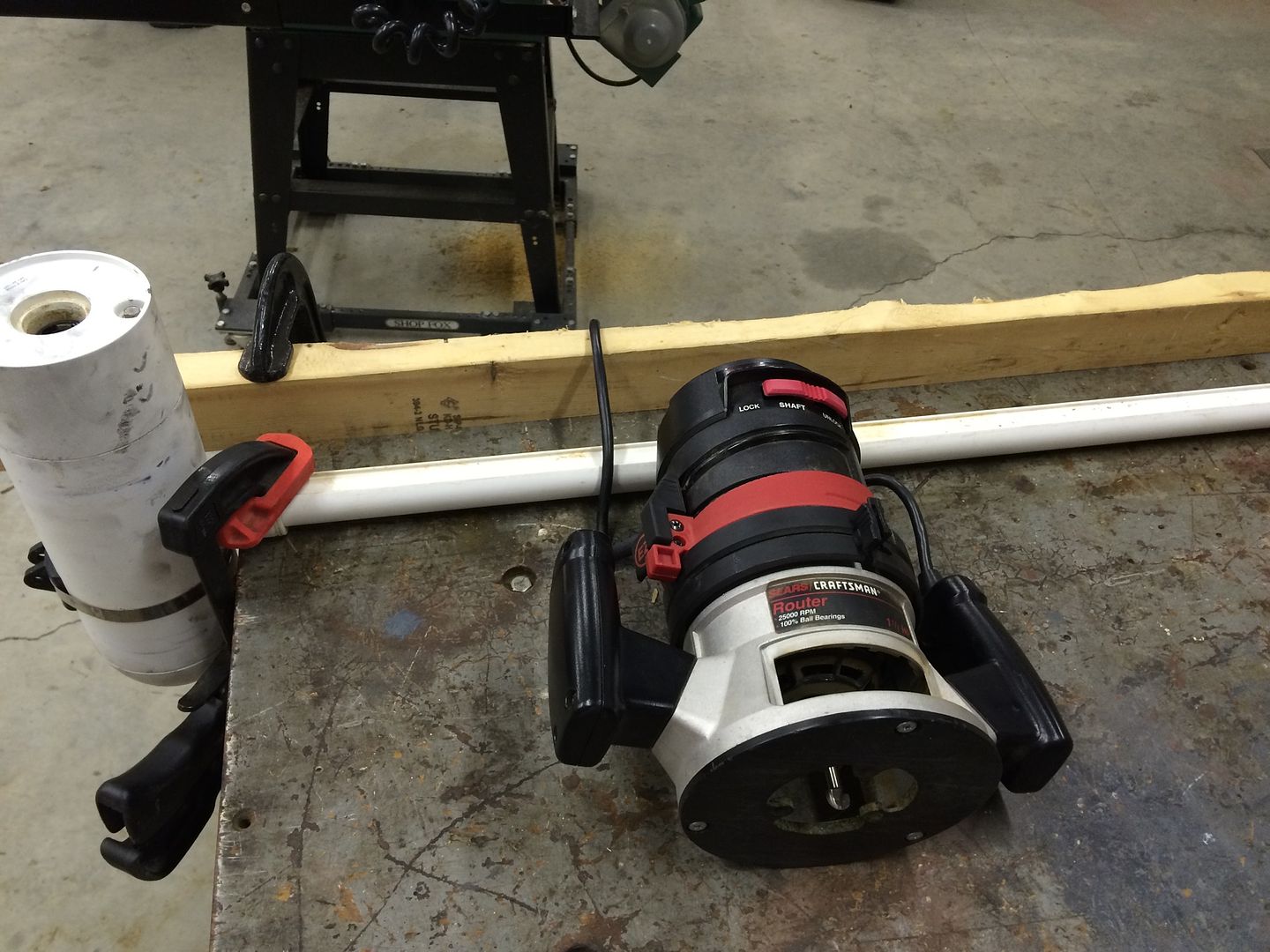 |
|
|
|
Post by mwardncsu on Oct 12, 2014 20:40:58 GMT -5
Yam documented this well. I did also ground my Trolling Motor battery bank to the battery where my electronics are connected. This seemed to be required in my case. When grounding that, put a 2 or 3A fuse on that wire as it is always possible that if you get grounds at different potentials you can get current flowing across that wire - and in the event of a short that wire could become a fire hazard. This wire does not need to be heavy - 16 gauge is fine - just fuse it. I did not (yet) fuse my wire in the trolling motor head (that grounds the TM motor casing to the TM ground terminal on the plug) - but I need to - I've read of cases where the positive brush wire inside the motor makes contact with the housing - this puts positive voltage on the casing when the motor is on - now with the casing grounded you create a direct short when the TM is powered up..... and the magic smoke would be let out as a result - fusing this wire at least protects against a potential direct short and potential fire..... if the fuse blows you lose the benefit of the ground, but at least you're safe. Before when I turned on the TM in manual mode it would black out the screen - and not in the "oh my gosh there are a million stripers under the boat, get the rods" way. I also could not have sensitivity above mid or even low 70s'. Now I can push it up to around 79-80 with a clear screen, and even at 82 with some "noise", when the TM is turned on you just see a minimal additional noise adder. 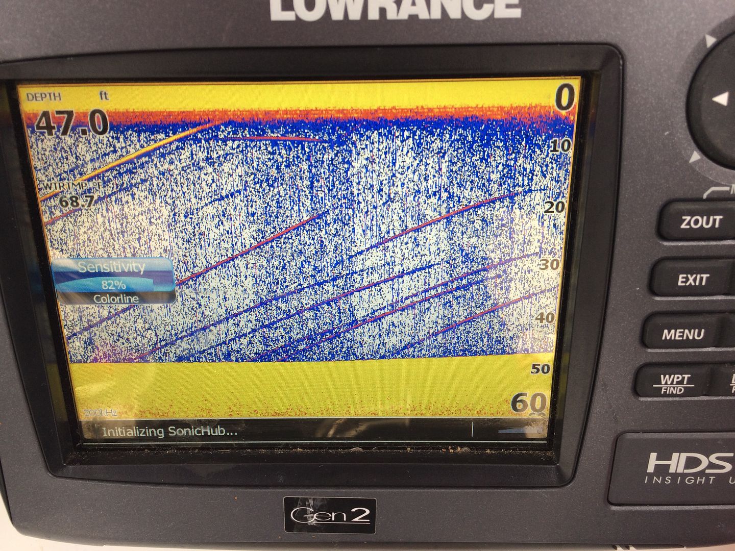 Actually here a few before.... 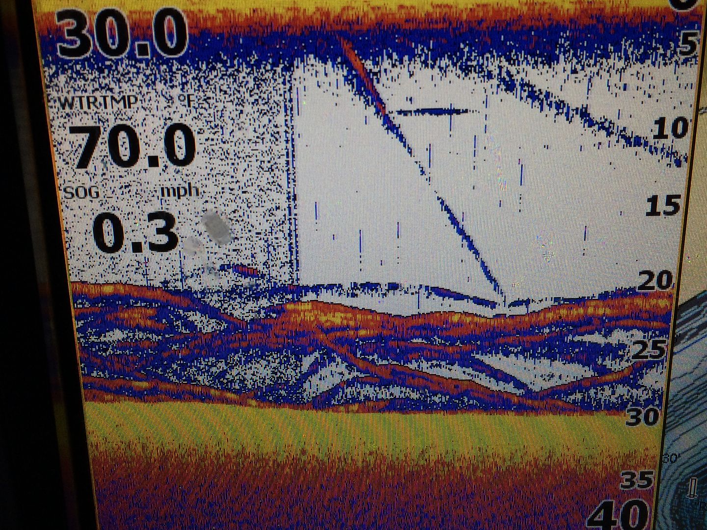 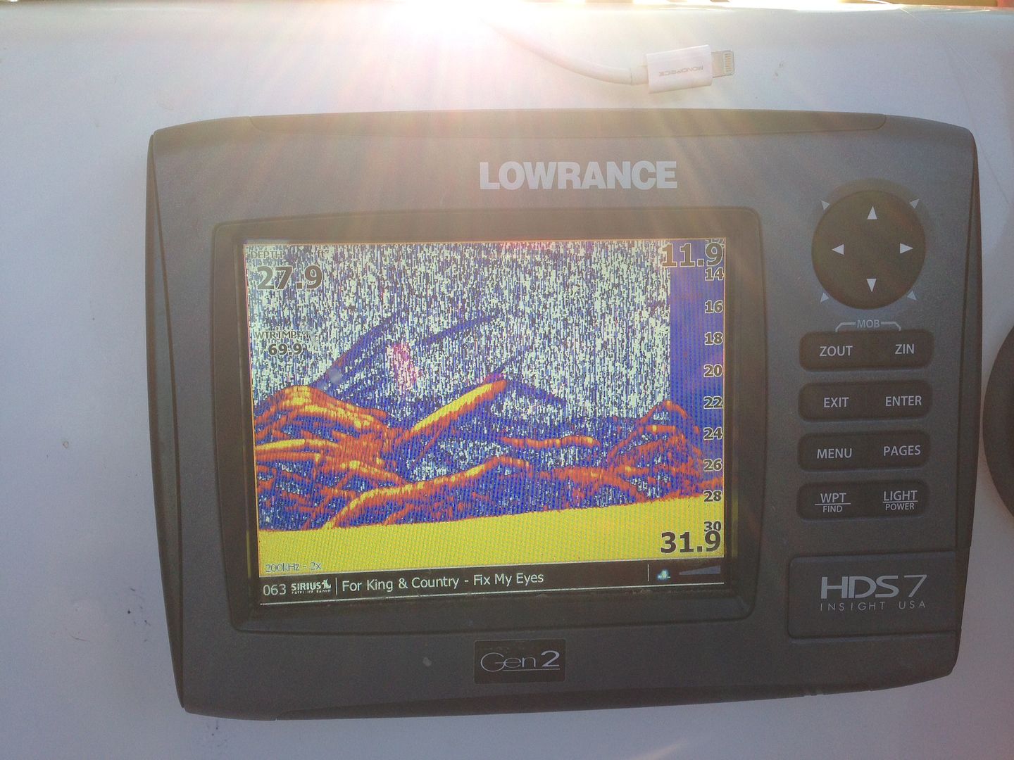 This is probably one of the better examples with fish - 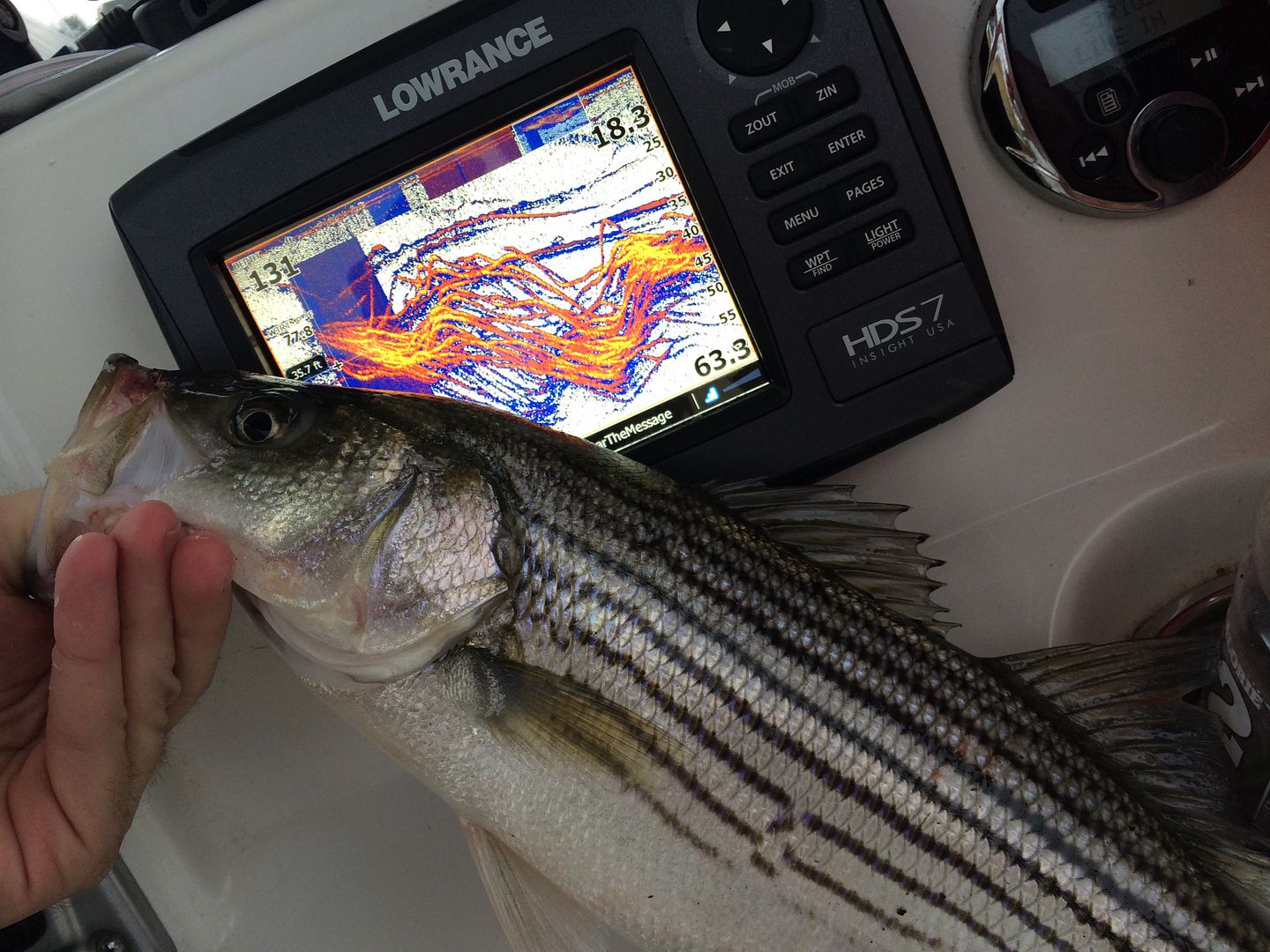 Not that big a deal you say? Well, that's in manual mode. When in Auto, the HDS was turning the sensitivity WAY down when the TM was on to get a nice picture - and it hid a lot of info - this screen shot should have been lit-up with yellows - and they barely showed up - if it had not been a ton of fish they might have been missed... 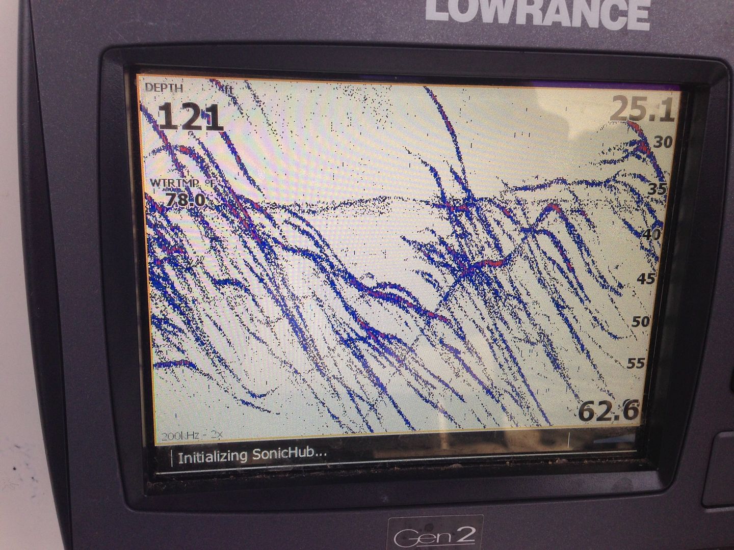 Now, the Auto mode should be able to do it's thing much better...... though I might try running manual for a while  |
|
|
|
Post by mwyatt1974 on Jul 28, 2021 14:30:59 GMT -5
Bringing a very old post back to life but this so far has been THE ONLY place I have found any decent info so thank you guys in advance and I am hoping and praying someone has the answer to a question.
I do not have a ground wire coming into my plug, only + and -. So my question would be running the ground to the skeg of the TM as discussed here, would that need to go directly to the - terminal of the cranking battery that also runs electronics or would I need to do something else?
|
|
Yam
New Member
Posts: 585
|
Post by Yam on Jul 28, 2021 20:11:26 GMT -5
Bringing a very old post back to life but this so far has been THE ONLY place I have found any decent info so thank you guys in advance and I am hoping and praying someone has the answer to a question. I do not have a ground wire coming into my plug, only + and -. So my question would be running the ground to the skeg of the TM as discussed here, would that need to go directly to the - terminal of the cranking battery that also runs electronics or would I need to do something else? With my old Riptide, I ran my ground wire to the negative of my TM plug. This meant that I was connecting it to the negative of of my TM batteries. My TM batteries were separate from my cranking and house battery. Honestly, I never saw much value from grounding my TM. It may have cleaned up some interference but not completely. I found that different speeds of the TM were worse than others. And luckily for me, my highest TM speed had the least interference. I hope this answers your question. |
|
|
|
Post by mwyatt1974 on Jul 29, 2021 7:15:37 GMT -5
Bringing a very old post back to life but this so far has been THE ONLY place I have found any decent info so thank you guys in advance and I am hoping and praying someone has the answer to a question. I do not have a ground wire coming into my plug, only + and -. So my question would be running the ground to the skeg of the TM as discussed here, would that need to go directly to the - terminal of the cranking battery that also runs electronics or would I need to do something else? With my old Riptide, I ran my ground wire to the negative of my TM plug. This meant that I was connecting it to the negative of of my TM batteries. My TM batteries were separate from my cranking and house battery. Honestly, I never saw much value from grounding my TM. It may have cleaned up some interference but not completely. I found that different speeds of the TM were worse than others. And luckily for me, my highest TM speed had the least interference. I hope this answers your question. Thanks very much for this detail. Given that wouldn't it be acceptable to put a fuse in the head of the trolling motor and attach the ground to the negative terminal there? I would think that is basically what MK does to their freshwater motors to ground them internally. Just would save on running a bunch of wire to my 24V bank. Unfortunately I do see a lot of interference and it doesn't clear the higher speeds just gets worse so having the pictures in this along with some youtube helped. Of course I won't know if it actually did any good till I get back to the lake and try it out. Thanks again! |
|